An arduino based chicken door

Introduction

Building an Arduino based chicken door is not a very complicated thing to do. There are several providers on the market but if you want to build it by yourself, you can easily do it. I have tried my best to keep everything as simple as possible.

Material

I use a Arduino Nano with an ATMega328P as the “brain” of the chicken door. At first I tried the ESP8266 for wireless connectivity, but that did not have enough digital in/ and outputs for all the sensors and switches.

Arduino Nano: https://amzn.to/2LD6QdN

The Motor driver powers the motor and lets you reverse direction

Motor driver: https://amzn.to/2K45nuX

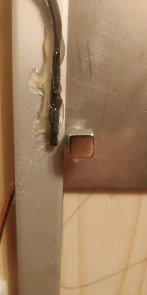
The reed-switches are used to find out if the door has hit it’s top or bottom end point.

Reed switch: https://amzn.to/34Y1JfM

The mini pushbuttons are used to control and configure the board

Mini Pushbuttons: https://amzn.to/34VJ3NR
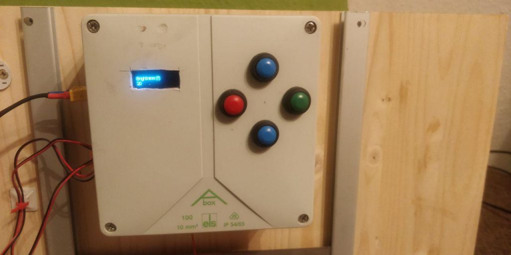
The user UI

OLED display: https://amzn.to/2Oglhbc

The light sensor is used to find out if it is dark or not.

Light Sensor: https://amzn.to/2Go7E35

As the Arduino Nano does not have a built in real time clock, we have to attach one so we can also control the door using times

Realtime Clock: https://amzn.to/2YdPeIK

The motor is used to move the door

Motor: https://amzn.to/2OhJs9h

Soldering Breadboard: https://amzn.to/2SDMhjp – use a regular one if you are not experienced.

A 200 Ohm resistor for the voltage divider (big pack here: https://amzn.to/2YrpAnG) but you really only need one!

Terminals to attach the switches: https://amzn.to/2Oqf0tk

H-Profile: https://amzn.to/2JOC8Ob

Rope: https://amzn.to/2SyEKCi

The door: https://amzn.to/2LFpbs8

These are all Amazon Affiliate links. When you buy using this link, I get a small share but your purchasing price does not change.

In addition, you need a couple of wires (for the breadboard and for the switches), tools like screwdrivers, drills and a handful of screws. If you want, you can also 3d-print your own box for that. If you design a nice box for the chicken door, please let me know and I’ll happily include the stl’s in my github repo.

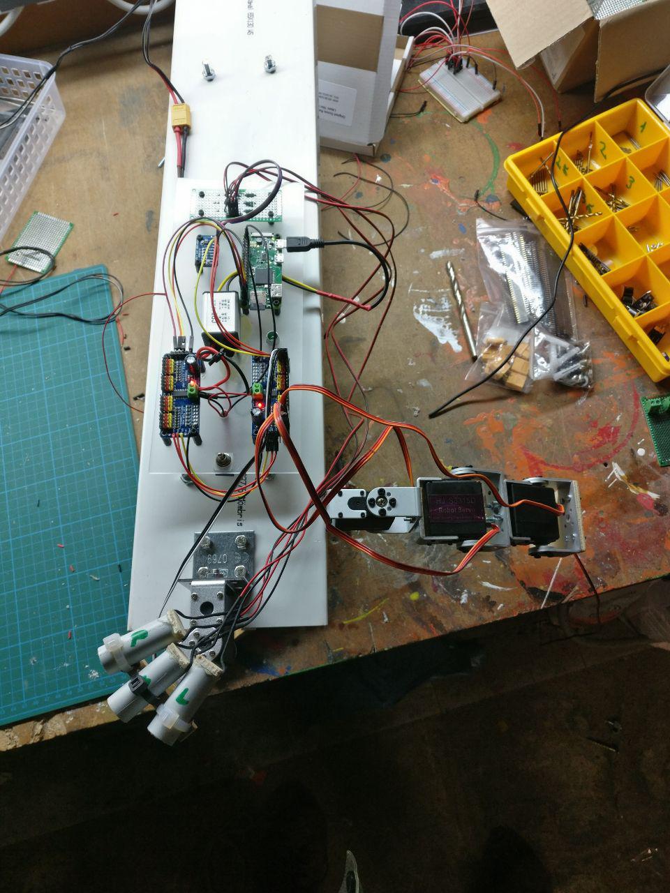
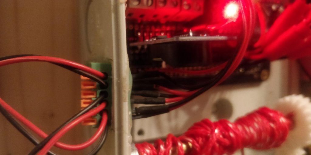
Putting the electronics together

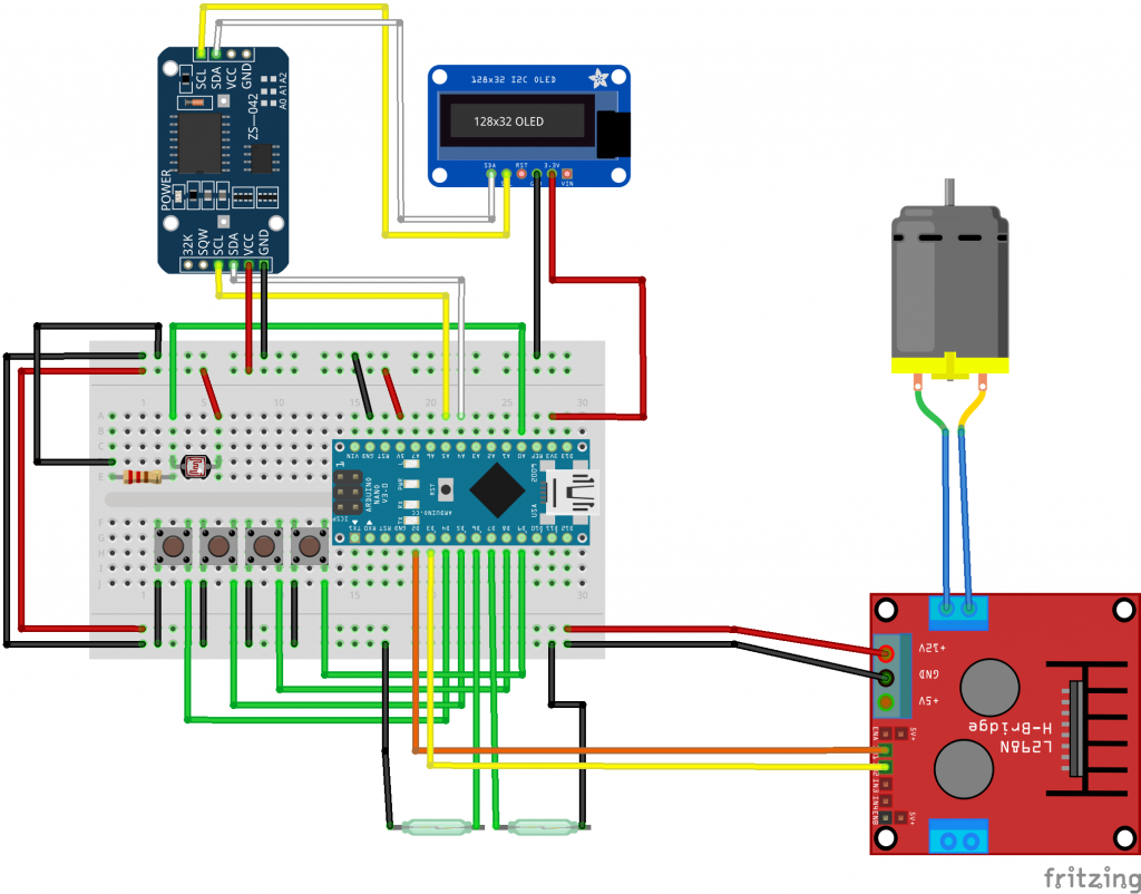
For soldering I use soldering breadboards (half size) as this greatly simplifies the cabelling/soldering.
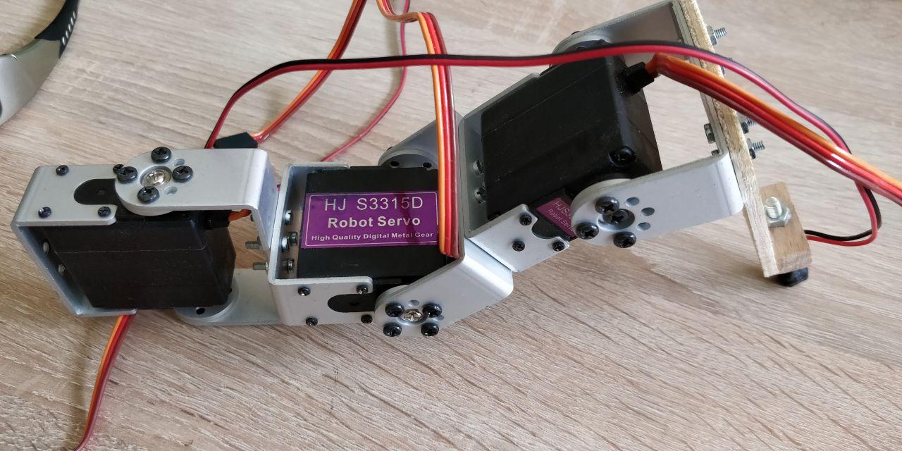
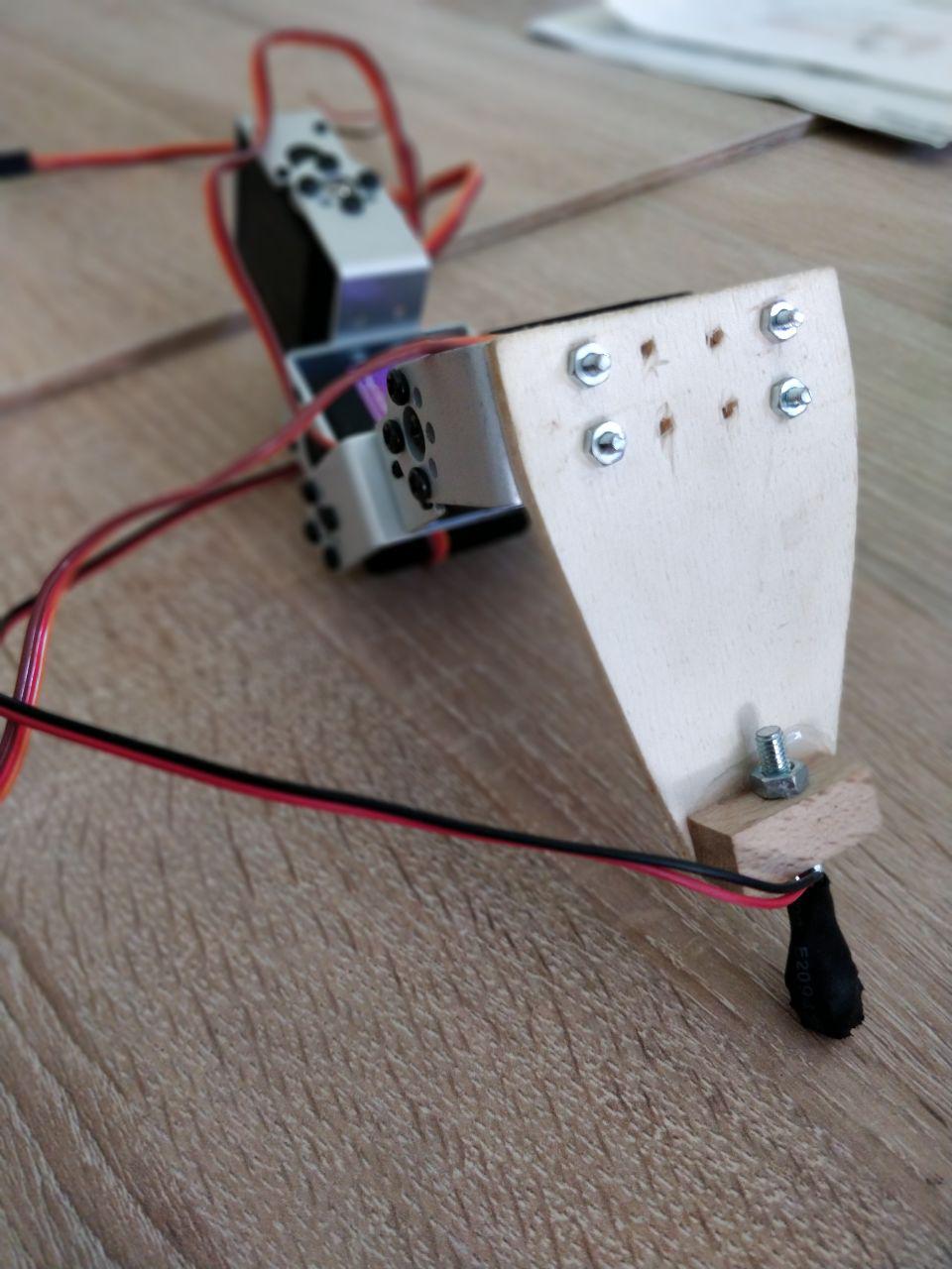
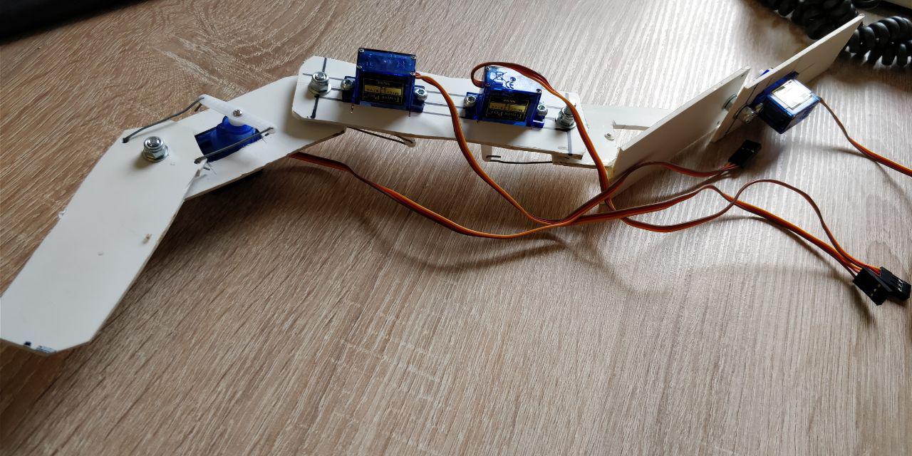
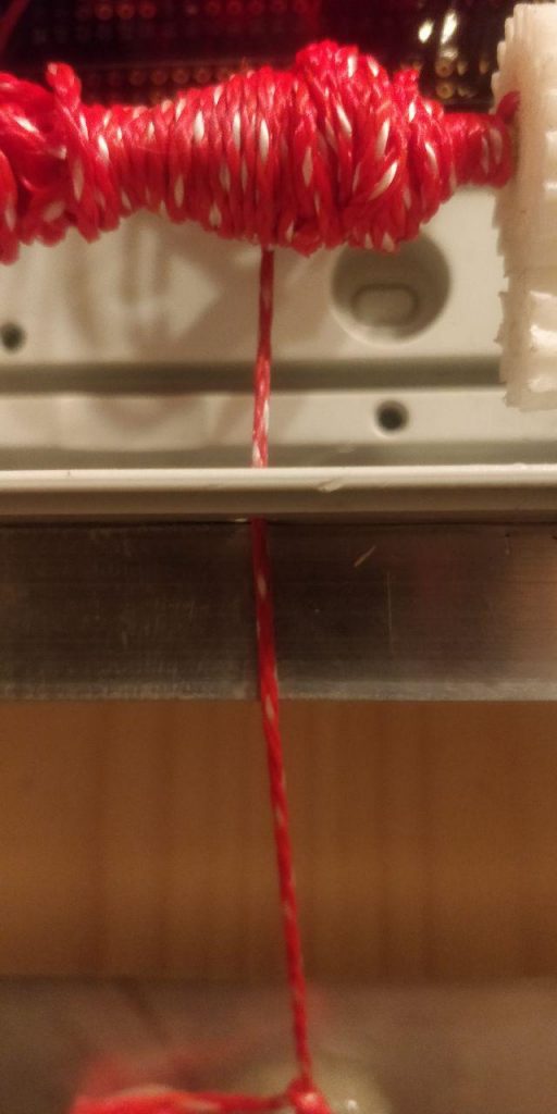
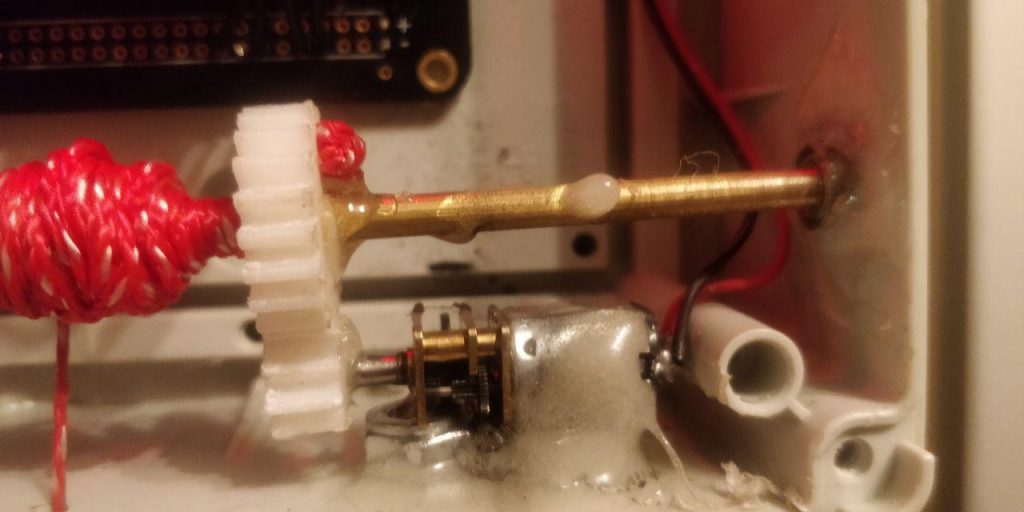
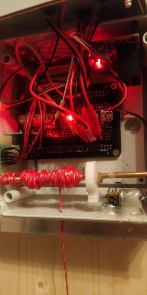
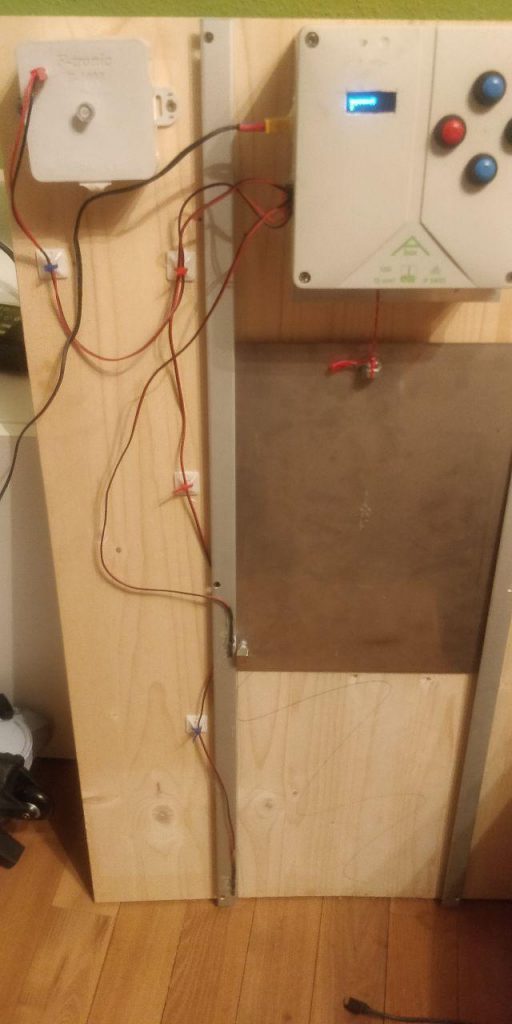
The mechanics

Here you see pictures of the testing setup. I leave it in the garden for now ti check if it behaves as expected. I don’t want to lock in the chicks 🙂

Make sure you put everything into closed box to avoid that mite sit in there. Do not use hot glue but prefer epoxy glue to put everything together

RTC Library

The library for the real time clock

Installing the RTC library

https://github.com/adafruit/RTClib

https://learn.adafruit.com/ds1307-real-time-clock-breakout-board-kit/overview

SSD1306 ASCII Library

A small library greatly simplifying the display of two lines on our display

https://github.com/greiman/SSD1306Ascii

The arduino code

I have set up a couple of tabs in the Arduino IDE as this keeps the code easy to understand.

Klappe1

the init code and the loop-function. At first I need a function prototype for set_display in order to support a default value for the second line. More on this in the display-section

Then I have set up a small block with the code you are most likely to modify when you don’t want to go too much into detail

// Values for opening/closing the door - configure only this…

int hours_open=07;
int minutes_open=30;

int hours_close=15;
int minutes_close=0;

int bottom_light_threshold=10;
int top_light_threshold=15;

Then I include the RTC and OLED libraries and create respective objects

#include <DS3231.h>
#include <Wire.h>
#include "SSD1306Ascii.h"
#include "SSD1306AsciiWire.h"

// DS3231 RTC
DS3231 Clock;

bool Century=false;
bool h12;
bool PM;
byte ADay, AHour, AMinute, ASecond, ABits;
bool ADy, A12h, Apm;

String date_delimiter=".";
String time_delimiter=":";

// SSD1306 OLED
#define I2C_ADDRESS 0x3C
#define RST_PIN -1
SSD1306AsciiWire oled;

Next I define the input/output pins

// Buttons
int btn_up_pin = 4;
int btn_down_pin = 5;
int btn_ok_pin = 8;
int btn_back_pin = 9;


// Reed switches (Door)
int sw_top = 6;
int sw_btm = 7; 


// Motor
int motor_pin1 = 2;
int motor_pin2 = 3;


// Light sensor
int lightsensor_pin=A0;

Define global variables with respective values

int light_intensity;                                 // Container for the currently measured light intensity
int flattened_light_intensity;
bool bottom_light_threshold_passed=false;            // flag if the threshold has been passed after the n measures
bool top_light_threshold_passed=false;               // flag if the threshold has been passed after the n measures

int number_of_light_measures=3;                      // number of measures
int measure_interval=5;                              // measuere every n seconds
int light_measures[3];
int second_measured;
int light_measure_counter=0;


// Idle Display variables
char* idle_display_content="flattened_brightness";   // brightness, flattened_brightness, datetime or temperature
String buf_line1;
String buf_line2;
int display_delay=1000;                              // delay after each interaction


// Door states
bool door_is_up=false;
bool door_is_down=false;


// Operating states (start in auto-state)
bool is_auto_state=true;

On the last line, the door is set to auto-mode. that means it follows the programme logic. If not in auto-mode, the door ignores times and only follows the up-down buttons.

The loop function

The loop-function controls the display and check if we are in auto-mode or not. If not, look at the buttons, if so, use time and brightness

void loop() {
  
  light_intensity=get_light_intensity();
  
  //idle display
  if(is_auto_state){
    if(idle_display_content=="flattened_brightness"){
      set_display("Brightness (f)",String(flattened_light_intensity));
    }
    if(idle_display_content=="brightness"){
      set_display("Brightness",String(light_intensity));
    }  
  
    else if(idle_display_content=="temperature"){
      set_display("Temperature",String(get_temperature()));
    }

    else if(idle_display_content=="datetime"){
      set_display(get_date_string(), get_time_string());
    }

    else if(idle_display_content=="off"){
      set_display("", "");
    }
    
  } else {
    set_display("Manual Mode!!");
  }
  
  
  //toggle the auto state on the green button. 
  if(buttonstate(btn_ok_pin)){
      set_auto_state(!is_auto_state);
  }


//auto mode - look at time/brightness to move the doors
  if(is_auto_state){  
    set_passed_threshold();
      
    if(door_should_be_open() and door_is_down){
      door_up(); 
    }

    if(!door_should_be_open() and door_is_up){
      door_down(); 
    }


// manual mode - use the buttons
  } else {  
    if(buttonstate(btn_up_pin)){
      door_up();
    }
    
    if(buttonstate(btn_down_pin)){
      door_down();
    }
  }

  
  delay(200);
}

Buttons

The Buttons-Tab contains simple logic to read from a digital input

// returns the state of the buttons

bool buttonstate(int buttonpin){
  int buttonState = digitalRead(buttonpin);
 
  if (buttonState == HIGH) {
    
    return false;
  } else {
    
    return true;
  }
}

Display

The display makes use of the set_display function prototype in the init section. The function controls the display.

  1. Checks if there is new data to be displayed.
  2. If so, replace the data in the buf_line1/2
  3. display the new text
// set the display. Comparing lines to display with lines already displayed to avoid flickering.

void set_display(String line1, String line2){
  if(line1!=buf_line1 or line2!=buf_line2){
    buf_line1=line1;
    buf_line2=line2;
    oled.clear();
    oled.println(buf_line1);
    oled.print(buf_line2);
  }
}

Door

This tab contains code to control the door and check the connected reed-switches

bool is_top(){
  return buttonstate(sw_top);
}

bool is_bottom(){
  return buttonstate(sw_btm);
}

void door_stop(){
  set_display("Stopping door");
  digitalWrite(motor_pin2, LOW);
  digitalWrite(motor_pin1, LOW);
  
}

void door_up(){
  if(is_top()){
    door_is_down=false;
    door_is_up=true;
    return;
  }
  digitalWrite(motor_pin1, HIGH);
  digitalWrite(motor_pin2, LOW);
  set_display("Moving up");
  while(!is_top()){
    if(buttonstate(btn_back_pin)){
      door_stop();
      delay(display_delay);
      set_auto_state(false);
      return;
    }
    delay(50);
  }
  door_stop();
  door_is_down=false;
  door_is_up=true;
  delay(display_delay);
  oled.clear();

}

void door_down(){
  if(is_bottom()){
    door_is_down=true;
    door_is_up=false;
    return;
  }
  digitalWrite(motor_pin2, HIGH);
  digitalWrite(motor_pin1, LOW);
  set_display("Moving down");
  while(!is_bottom()){
    if(buttonstate(btn_back_pin)){
      door_stop();
      delay(display_delay);
      set_auto_state(false);
      return;
    }
    delay(50);
  }
  door_stop();
  door_is_down=true;
  door_is_up=false;
  delay(display_delay);
  oled.clear();

}

bool door_should_be_open(){
  
  int opening_minutes=calc_minutes(hours_open, minutes_open);
  int closing_minutes=calc_minutes(hours_close, minutes_close);
  
  if((opening_minutes<=get_current_minutes() and top_light_threshold_passed) and (closing_minutes>=get_current_minutes() or bottom_light_threshold_passed)){
    return true;
  }
  return false;
}

void set_auto_state(bool state){
  is_auto_state=state;
  if(state){
      set_display("Mode","Auto");
      delay(display_delay);
    } else {
      set_display("Mode","Manual");
      delay(display_delay);
    }
}

the most important one here is door_should_be_open(). Here is a good point to add Serial.println’s to troubleshoot any errors in the doors behaviour.

Light

The light tab does everything that is related to the light – read the value of the light sensor, flattens the read values and sets flags when top or bottom light thresholds have been passed.

int get_light_intensity(){
  return analogRead(lightsensor_pin);
}

// check if the light has passed the threshold. If so, set global var to true. If not, set to false
// The number of measures and the interval is set in the klappe-tab

void set_passed_threshold(){
  if(Clock.getSecond() % measure_interval == 0 and second_measured != Clock.getSecond()){ 
    second_measured=Clock.getSecond();
    light_measures[light_measure_counter]=light_intensity;
    light_measure_counter++;
    if(light_measure_counter==number_of_light_measures){
      int sum=0;
      for (int i = 0; i < number_of_light_measures; i++){
        sum+=light_measures[i];
      }
      light_measure_counter=0;
      flattened_light_intensity=sum/number_of_light_measures;
      
      // top threshold
      if(sum>=top_light_threshold*number_of_light_measures){
        top_light_threshold_passed=true;
      } else {
        top_light_threshold_passed=false;
      }

      //bottom threshold
      if(sum>=bottom_light_threshold*number_of_light_measures){
        bottom_light_threshold_passed=true;
      } else {
        bottom_light_threshold_passed=false;
      }
    }
    
     
  }
}

Setup

The setup-tab does all the initialisations of the hardware and displays a small greeting to the chicken

void setup() {
  Serial.begin(9600);
  Serial.println("Starting Setup");

  
  // set pin modes
  Serial.println("Pinmodes");
  pinMode(btn_up_pin,INPUT_PULLUP);
  pinMode(btn_down_pin,INPUT_PULLUP);
  
  pinMode(btn_ok_pin,INPUT_PULLUP);
  pinMode(btn_back_pin,INPUT_PULLUP);
  
  pinMode(sw_top,INPUT_PULLUP);
  pinMode(sw_btm,INPUT_PULLUP);

  pinMode(motor_pin1,OUTPUT);
  pinMode(motor_pin2,OUTPUT);

  
  // Start the I2C interface
  Serial.println("I2C");
  Wire.begin();
  Wire.setClock(400000L);


  // Start the the OLED
  Serial.println("OLED");
  #if RST_PIN >= 0
  oled.begin(&Adafruit128x32, I2C_ADDRESS, RST_PIN);
  #else // RST_PIN >= 0
  oled.begin(&Adafruit128x32, I2C_ADDRESS);
  #endif // RST_PIN >= 0
  oled.setFont(Arial14);

  // Use true, normal mode, since default for Adafruit display is remap mode.
  oled.displayRemap(true);
  oled.clear();


  // lower door as a start and greet whoever is there.
  set_display("Hello","Ladies");
  delay(3000); 
  door_down();
  
  Serial.println("End of Setup");
}

Temperature

The temperature tab contains a very small function to read from the temperature sensor that is built into the real time clock

//temperature

int get_temperature(){
  return Clock.getTemperature();
}

Time

The time-tab contains a couple of functions to calculate the number of minutes into the day and build the Date/Time strings for the display.

int get_current_minutes(){
  int current_minutes=(Clock.getHour(h12, PM)*60)+Clock.getMinute();
  return current_minutes;
}


// Multiply hours with 60 and add minutes
int calc_minutes(int hour, int minute){
  int calc_minutes=(hour*60)+minute;
  return calc_minutes;
}


// Build the date string
String get_date_string(){
  int clock_day=Clock.getDate();
  int clock_month=Clock.getMonth(Century);
  String day_string=pad_two(clock_day);  
  String month_string=pad_two(clock_month);
     
  return day_string+date_delimiter+month_string+date_delimiter+"20"+String(Clock.getYear());
}


// Build the time string
String get_time_string(){
  int clock_hour=Clock.getHour(h12, PM);
  int clock_minute=Clock.getMinute();
  int clock_second=Clock.getSecond();
  String hour_string=pad_two(clock_hour);
  String minute_string=pad_two(clock_minute);
  String second_string=pad_two(clock_second);

  return hour_string+time_delimiter+minute_string+time_delimiter+second_string;
}


// Function to pad with zero to two characters. 
String pad_two(int nbr){
  String out;
  if(nbr<10){
    out="0"+String(nbr);
  } else {
    out=String(nbr);
  }
  return out;
}

Resources

You will find the full code, stl-meshes for the gears and the fritzing file in my github-repository. If you have any improvements please feel free to adjust the code as needed and send me pull requests for discussion. I am not a C++ pro, so I’d be happy about feedback.

If you build this, please send pictures of it and if you have and problems putting this together, let me know. If you need a better explanation of the code, I will add it here.

Cheers and thanks for reading all this

Andre

Building a hexapod robot – from nothing to a first platform

Hi All,

back to my blog series about my hexapod robot that I’m working on for about 7 months now. This is the continuation of this article about servo control, leg prototypes and inverse kinematics

The platform

At first I tried to build a platform and legs from wood of which I found out very early that it’s not sturdy enough while being a lot too heavy. Then I went with parts of a cable duct which were really light but much to easy to bend.

I decided early that I needed something tougher. I went with steel from my local diy market and came up with this…

adding a bit of plastic from an old cable duct, plastic spacers and all electronics I figured I would need, this was the first platform:

intermission: purposes

the main reason to build this robot learning. I wanted to learn about electronics, raspberry pi, math and geometry, python and many other things.

But the robot also needs something to do. Just walking was not an option as that seemed “too simple” to me when I first thought about that (it is not!). So here are the missions I was thinking about:

Follow a light

The idea was to use 3 pipes, each with a light depending resistor inside and attach it to a servo. If the left pipe receives more light, move the servo to the left and so on. If both receive the same amount of light, read the servos current value and turn the robot until the servo is in a zero position. If unclear, traverse from left to right. That was surprisingly easy (in this video I have turned on the flashlight of the phone to act as an attractor)

I don’t even know why I abandoned the idea. It’s still there and would be easy to implement.

Avoid obstacles

another classic for robots. Walk along until you get too close to an obstacle, then turn around and find your way around that. That’s one thing that will be possible with the current design

Identify and climb stairs

That’s a tough one. Identifying stairs and climbing them is quite a logical challenge to solve using only distance sensors. Not sure, if this will be done

Go “somewhere” autonomously

The robot would need to identify where it is and then autonomously find it’s way to the destination. That’s another nasty one of which I have no idea how to implement.. Sounds very interesting though

…to be continued….

Quickfix: Pentaho client tools and the Java MySQL connector

Hi all,

when you want to install the Pentaho client tools to your machine and you have trouble connecting to a MySQL database, there are a few things to keep in mind:

1. the Pentaho-Tools do not ship with a Java MySQL connector. You have to download it from the MySQL website.
2. the latest connector from the MySQL website does not work (versions 8.x)
3. mysql-connector-java-5.1.47 works well for me. Install it by copying it into the respective “lib” / “lib/jdbc” folders

Then your client tools should be working fine.

cheers

Andre

Quickfix: Import your nextcloud addressbook into twinkle

Hi All,


I just switched to the twinkle-softphone and found that there is no way to import anything into the addressbook. I am currently learning python so I thought this is a nice little project to work on. Note that this only works on python 2.

Tested on Ubuntu 16.04LTS, Ubuntu 18.04,  Nextcloud 13 and TWINKLE 1.9.0

It works for me and may not work for you. Please comment if you have any issues with this.


#twinkle addressbook importer for nextcloud

nextcloud_protocol="https://" 
nextcloud_username="your_nextcloud_username"
nextcloud_password="your_nextcloud_password"
nextcloud_url="the_nextcloud_url"

#############################################################
import urllib
from os.path import expanduser
import os.path
from shutil import copyfile

# get the home path
home = expanduser("~")

#build the twinkle addressbook path
twinkle_phonebook_path=home+"/.twinkle/twinkle.ab"

#create a backup if a file exists
if(os.path.isfile(twinkle_phonebook_path)):
    copyfile(twinkle_phonebook_path, twinkle_phonebook_path+".bak")

#open the addressbook file
file=open(twinkle_phonebook_path,"w")

# build the nextcloud URL
url=nextcloud_protocol+nextcloud_username+":"+nextcloud_password+"@"+nextcloud_url+"/remote.php/dav/addressbooks/users/"+nextcloud_username+"/contacts?export"

#load the VCF Data
try:
    response = urllib.urlopen(url)

except:
    print("Error!");
    exit()

else:
vcf = response.read()

#go through the lines in the vcf-document 
for line in vcf.splitlines():

    #check if it's a "full name" line
    if line.startswith("FN"):
        r=line.split(":")
        full_name=r[1];
        names=full_name.split(" ")
        first_name=names[0]
        if len(names)==1:
            last_name=""
        else:
            last_name=names[1]

    #check if it's a phone number line
    if line.startswith("TEL;TYPE"):
        r2=line.split(":")
        phone_number=r2[1]
        r3=r2[0].split("=")
        phone_type=r3[1]

        #write new line to file. 
        this_line=last_name.strip()+"||"+first_name.strip()+"|"+phone_number.strip()+"|"+phone_type.strip()
        file.write(this_line+"\n")

#close the file
file.close()


Quickfix: Fixing basti2342’s retweet bot

Hi All,

just a really quick one: basti2342’s retweet bot (found here) is missing a configuration file for it to work. The file in question should be called “config” (no extension) and be put into the root directory of the bot (along with the retweet.py file). The contents should be as follows:

[settings]
search_query:#hashtag
# Leave empty for all languages
tweet_language:
number_of_rt:10

[twitter]
consumer_key:consumerKey
consumer_secret:consumerSecret
access_token:accessToken
access_token_secret:accessTokenSecret

In addition you might have to install configparser

pip install configparser

With that, your bot should run smoothly

Cheers

Andre


Building a hexapod robot – more building and a lot to learn

Howdy all,

here I continue my report about the hexapod robot journey.

more building and a lot to learn

So I had a couple of problems to tackle

  • too many cables
  • randomly moving servos
  • learn python as the language of choice for robotics on a pi
  • build a better prototype leg
  • how the hell does a “step” work for a robot leg?

Too many cables and servo jitter

Moving servos using the GPIO ports and simulate a PWM signal with them is just a lot of work and absolutely unreliable. A bit of research brought me to this little toy: The PCA9685, a I2C driven servo motor controller.

It can run 16 servos per unit and has a external power supply so the servos are not run by the Raspberry PI’s internal power. It is controlled by the I2C bus on the Raspberry Pi, so it really only needs four cables to work. This is the tutorial I used to get started with the controller. If you are planning to buy one, make sure you buy one with pre-installed pins 🙂

Build a better prototype leg

so I started looking for better servos and a good way to build a leg from them. With normal servos like this  it’s really hard to attach something to it. I wanted to avoid using 3D printed parts as I wanted my bot to look self-made and punky. After more searching I found these

servos that have a though-going axis and aluminum brackets delivered with them. Using a couple of 3mm screws I was able to create a leg prototype that looked really nice.

I added a push-button to the end of the leg just for testing if this would make sense. I thought I could use it to find out, if the leg has actually touched the ground.. Did it work? We’ll see in a later chapter.

How does a “step” for a robot work

OK so we have three servos. Basically a hip, a knee and an ankle. The shoulder is turned 90° for forwards/backwards motion.

I was never really good at maths, so I figured that somebody must have done this before. Kudos to Oskar Liang for putting this together.

After a bit of fiddling around, the leg started moving somewhat natural, so I decided that now it’s a good time to put together a hexapod.

…to be continued…

Building a hexapod robot – the beginning

Howdy folks,

in my portfolio it says that I am exploring robotics and I have spent half a year now trying things out, building and rebuilding prototype legs, platforms and learning python. Well: I do have a blog and I thought now it’s a good time to share my experiences so far. Unfortunately my phone broke along the way, so I do not have many pictures of the early stages of the project.


The beginning

I started the project in June 2017 without a real plan, what I wanted to do. I knew that I love the raspberry-concept and that I hate, when after-work projects stay inside the computer. I love it, when I have some kind of interaction with the real world. I have already done a few projects with IP Cameras and gphoto2 and I always wanted to do more of interaction and not only consumption.

OK – let’s see if I can move a servo.  So I ordered a set of really cheap servos, a breadboard and a raspberry pi zero W on amazon. I did a bit of Google research and found that you can easily control a single servo using the standard GPIO ports of the PI. I quickly noticed that this is not really feasible.

  • The servo does a lot of unintended movement
  • There is a LOT of cabelling involved and things get complicated and error-prone really quickly
  • as soon as the servos drag too much power, the pi will probably explode

But hey – the servo moved and I got caught in the cobweb of mediocre electronics. So I started to build a simple leg using a bit of plastic, wire and hot glue and was able to more or less control it through the GPIO ports.

Leg Prototype

After a bit of fiddeling around, I was able to move the leg the way I wanted.

OK that really caught me. My brain was boiling with legs, platforms, API’s, AI,… The plan to build an autonomous hexapod robot was born…

….to be continued….

Sharing Responsibilities – JaRE installation

Hi All,

during PCM17, the Pentaho community meeting, I watched Uwe Geercken’s presentation about his Java Rule Engine (JaRE). The idea is to have business users maintain their own business rules and have the IT department only take care of IT logic. That should take load off IT’s shoulders and give power to the business users. As the business users are the business experts, data quality should improve as the rules are maintained directly by the business.

I am a Pentaho heavy user, so I will focus on the use with Pentaho data integration (PDI/Spoon/Kitchen). The rule engine can also compare the rules against an Apache NIFI stream, an Apache KAFKA stream and inside virtually any other Java application. JaRE is open source, available on Github, and can be used under Apache License 2.0

This blog post will cover the installation of the JaRE. In the coming days I will continue writing about maintaining the rules and about the PDI integration and usage.

JaRE Installation

I will install the JaRE on a clean UBUNTU 16.04.3 LTS virtual box. The OS is fully updated.

First of all we need to install the Tomcat Server, MariaDB-Server and GIT.

sudo apt-get install tomcat mariadb-server git

Next, we enter MariaDB

sudo mysql -uroot

and create the database and a maintaining user. Of course you should pick a more secure password. Just make sure to remember it. You’ll need it during the installation process.

CREATE DATABASE ruleengine_rules;
CREATE USER 'rule_maintainer'@'localhost' IDENTIFIED BY 'maintainer_password';
GRANT ALL PRIVILIGES ON ruleengine_rules.* TO 'rule_maintainer'@'localhost';
FLUSH PRIVILEGES;

Exit MariaDB with ctrl+c

Now we download the ruleengine maintenance sql file to our filesystem and load it into the database we have just created

git clone https://github.com/uwegeercken/rule_maintenance_db.git
sudo mysql ruleengine_rules -uroot < rule_maintenance_db/ruleengine_rules.sql

The database is installed now.

Next step is to download the ruleengine maintenance war file and copy it to the tomcat server

git clone https://github.com/uwegeercken/rule_maintenance_war.git
cp rule_maintenance_war/rule_maintenance.war /var/lib/tomcat8/webapps

Now you can access the rule maintenance tool at

http://localhost:8080/rule_maintenance

On first start, the engine asks for the MariaDB username/password provided earlier and a path where you want to save the rule files.

Click ‘save’ to check the database connection. Next click Login. The default username is “admin”, the password is also “admin”

This concludes the installation tutorial. The next blog entry will be about maintaining the rules.

Update 12/2017

The installation process has been simplified now. There is no need any more to run the SQL file.


PCM17 – the Pentaho Community Meeting 2017

Hi All,

this Saturday, the #PCM17 takes place in Mainz, Germany. PCM17 is the Pentaho Community Meeting that takes place at different locations around the globe. As it happens “around the corner” this time, I will be there and I am so excited. This is the 10th time it happens and there are so many interesting talks. As there are two different “Tracks” – Business and Technical, I will have a hard time deciding where to go – I will mostly stick to the technical track though.

There are talks about the separation of business- and IT rules in ETL Jobs, “Serverless” PDI and Machine Learning, a topic I am specifically interested in.

And – hey – CERN is talking and if there is anybody in the world that generates a lot of data it needs to handle, it’s CERN.

IT-Novum, who is organizer of the event, will do extensive blogging, so I will just lean back and enjoy the show – nothing to expect in my blog.

Follow me on Twitter for comments, impressions and pictures.

Cheers

Andre

Pentaho is now Hitachi Vantara…

..but according to Pedro Alves, our community superhero, Pentaho CE will stay. A couple of links:

http://fortune.com/2017/09/19/hitachi-vantara-data-systems-pentaho/

https://pedroalves-bi.blogspot.de/2017/09/hello-hitachi-vantara.html

https://globenewswire.com/news-release/2017/09/19/1124774/0/en/Hitachi-Introduces-Hitachi-Vantara-A-New-Digital-Company-Committed-to-Solving-the-World-s-Toughest-Business-and-Societal-Challenges.html#.WcFayuVTg8U.linkedin

They will probably tell us more at the Pentaho Community Meetup (#pcm17).