This tutorial was re-posted from http://oscarliang.com, an amazing resource about robotics and drones. Check them out and follow them on twitter.
Inverse Kinematics Basics Tutorial – Oscar Liang
What is Inverse kinematics in robotics? With your robot having legs the position of those legs dictates where its feet are. Where its feet are dictate its point of balance.
As you might know “balance” can be defined as the robot’s centre of mass (affectionately referred to as its centre of gravity) being between its centre of pivots (i.e. the edges of where its feet contact the ground). If the centre of mass is above the centre of pivots and between them the robot will balance (almost an unstable equilibrium, if you’re an applied mathematician. If the centre of mass is above but outside the centre of pivots (i.e. beyond the edges of his feet) the robot will overbalance and fall.
If you feel confident about the Inverse Kinematics basics, you can jump to
Implementation of IK on Hexapod robot:
https://oscarliang.com/inverse-kinematics-ik-implementation-for-3dof-hexapod-robot/
here is an implementation of a 3 DOF hexapod robot which I built using IK:
https://oscarliang.com/hexapod-robot-with-3-dof-legs-degree-of-freedom/
Kinematics and Robots?
If you’re a little unclear about Robot Kinematics, I recommend to start with something basic, a cube is a good start, and imagine that its centre of mass is right in the middle (which it will be if its density is even throughout). When the cube is just sat there it’s stable. The centre of mass is above the centre of pivot (the edges) but because it’s between them (when viewed from every direction) it will just sit there until you prod it.
Now you prod it and slowly tilt it. As the centre of mass approaches a point directly above one of the edges (our centre of pivot) the cube will feel lighter to your touch and if you can get the centre of mass directly over that centre of pivot it will balance. As soon as you push it past that point, so the centre of mass is the other side of the centre of pivot it will fall.
The robot is exactly the same. This is why the kinematics of the feet are important to you. If you want the robot to balance dynamically you NEED to know where the feet are and where they’re going to need to be. Please understand that I’m not going to do all your work for you, so the code or equations I share are not guaranteed on their accuracy but purely a demonstration of how the method is derived and works.
Forward and Inverse Kinematics – FK & IK
Forward kinematics is the method for determining the orientation and position of the end effector (x,y,z) coordinates relative to the centre of mass , given the joint angles and link lengths of the robot arm (servo positions). This equation is deterministic. You know absolutely from the servo positions exactly where the foot is.
Inverse kinematics is the opposite of forward kinematics. This is when you have a desired end effector position, but need to know the joint angles required to achieve it. This is harder than FK, and there could be more than one solution.
The FK is not very useful here, because if we are given a change of angle of a servo, only one effector moves in the chain. But if we are given a change of coordinate, the whole chain of effectors (servos) might have to move a certain angle for the end point to reach the desired position. And also the movement tend to be more natural as well!
Approaches To Solve IK
There are two approaches to solving inverse kinematics:
- Analytical – requires a lot of trigonometry or matrix algebra
- Iterative – better if there are lots of links and degrees of freedom.
Analytical approach
If there are only two or three links then it may be possible to solve it analytically. One possibly might be to draw out the arm with the angles shown on it, then solve for the angles using geometry. The problem is that this is not really a very general approach.
Another analytical approach is to represent each links rotation and translation by a matrix. The end point is then given by all these matrixes multiplied together, so we just need to solve this matrix equation. Then find what rotation each matrix represents.
There may be many solutions or there may not be any solutions. In other words there are lots of ways to reach to a given point, or it may be out of reach.
If there are many solutions, then you might need to apply additional constraints. For instance, human joints can only bend within certain limits.
Iterative approach (not important)
This is a more general approach for programming complex chains. It might be useful if you are building a snake robot or only if you are interested reading. :-p
Start off with the joints in any position, then move each of the joints in turn, so that each movement takes the endpoint toward the target
Starting with the joint nearest the end point, rotate the joint so that the current end point moves toward the required end point. Then do the same with the next joint toward the base and so on until the base is rotated. Then keep repeating this, until the end point is close enough to the required end point or if further iterations are not moving it closer to the required point.
It may be possible to have a more realistic strategy than this, for instance, if I am using my arm to pick up an object then, if the object is a long way away, I will move the bigger joints in the arm, then as the hand gets closer the smaller joints of the hand are used for the fine adjustments.
The angle of rotation for each joint is found by taking the dot product of the vectors from the joint to the current point and from the joint to the desired end point. Then taking the arcsin of this dot product.
To find the sign of this angle (ie which direction to turn), take the cross product of these vectors and checking the sign of the Z element of the vector.
Because we will be mainly dealing with 3DOF hexapod or Quadurped robot legs, Analytical, or simple trigonometry would do the trick for now.
Some Real Work
Enough theory, to turn this into progamming language, you’ll have to remember that the angles are unknown, and we need to work it out using equations and trigonometry.
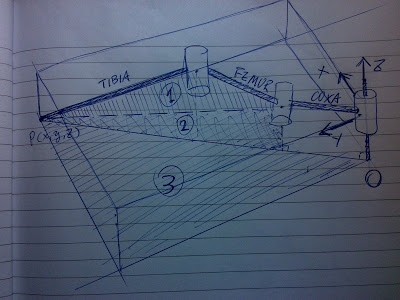
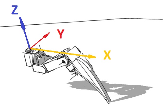
So, first thing is going to be simplify this problem from 3D into two 2D problems, to solve for α (alpha), β (beta) and γ (gamma).
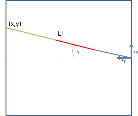
Gamma is easy, from diagram one, we have:
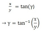
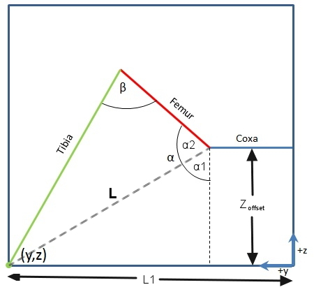
Now that you have gamma, you have two more angles to solve (and they are in the same plane)let’s move on to the second diagram.
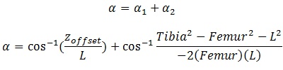
Alpha is a bit tricky, so I tend to split it into Alpha1 and Alpha2.
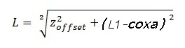
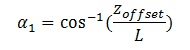
We can get Alpha1 by working out L first.
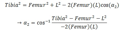
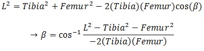
For Alpha2 and Beta, we need some help from Cosine Rules:
From these formula, if we know 3 sides of a triangle, we can find out any angles inside it. Don’t doubt it, it just works! 🙂
So now we have Alpha2,
And Alpha is
And Finally, Beta
At that point, you have your values for your servos!
Source: Inverse Kinematics Basics Tutorial – Oscar Liang